Geological maps have many drawn elements (layers, faults, contacts, etc.) that can be assimilated to planes. The orientation of these planes is the key to determine geological structure of grounds in depth. A way to locate in space any plane is to determine the orientation of the line of maximum slope contained in it (also known as the plane dip). This line (through which water would flow or a cobblestone would roll, etc.) is the one that has the highest angular value with regard to an imaginary horizontal plane (fig. A.).
Figure B shows other lines on the same plane that have not the maximum slope. The line of zero slope (minimum) is the plane direction and is by definition perpendicular to the maximum slope line (fig. C.) It represents the intersection of the inclined plane with an horizontal one.
In order to characterize the maximum slope line (fig. A) it will be necessary to calculate two angles: the dip direction (where the plane inclines to) and the dip angle (i.e. the plane inclination.) The dip direction is the angle between the geographic north and the projection of the maximum slope projection on an horizontal plane. In this case it is to the East (the plane direction is North-South.) The angle of dip is the angle that forms the maximum slope line with an horizontal plane. In fieldwork these two parameters can be respectively measured with a compass and a clinometer.
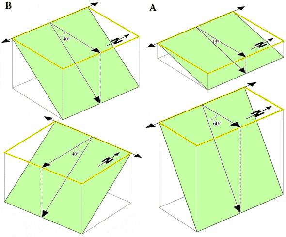 To understand better these two parameters you can see the following figure where (A) planes with different dip angles (15º and 60º) but with the same dip direction (to the East) and planes (B) with the same angle of dip (40º) and different dip direction (to the East ant to the South) are shown.
A simplified way to transmit these measurements is to give the dip direction, that is the angle that the maximum slope line projection has related to the North (always measuring clockwise) and afterwards, separated by an inclined bar, the dip angle. In the case of figure A is 090/15 (on the top of the example) and 090/60 (on the bottom) and 090/40 and 180/40 in figure B.
The following symbols are used in geological maps to describe the orientation of stratification (see also Contact types):
Horizontal layers are represented by an equal-arm cross.
Inclined layers are represented by an elongated line (that follows the plane direction). From the centre of this line a shorter one comes out and indicates the dip direction of the plane. In this case you also must write down the value of the inclination or dip angle.
Vertical layers are represented with a different-arm cross. The longest coincides with the layer or plane direction.
Overturned layers (those that have been inclined more than 90º) are represented as inclined layers but with a semicircle that comes out from the plane direction line.
The blocks of the following figure show three-dimensional horizontal layers or geologic units (A), vertical (C) and inclined ones (B and D), all of them concordant and correlative. The upper part of the block represents the geological map ‘without relief‘ with the symbol that indicates the spatial orientation of the several planes. The plane that separates a unit from another on the map corresponds to a line represented with a concrete symbol system (see Contact types.) Different orientation of layers can be seen on both sides of the blocks that represent two geologic cross sections made in perpendicular directions. Normally, if any other information is given, layers are ordered from the oldest (in the lower part) to the newest (upper part) using a numerical (1, 2, 3, 4…) or alphabetical (a, b, c, d…) correlative notation.
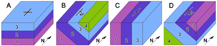
Block D shows inclined layers that have the peculiarity that the order that they display (4, 3, 2, 1) is different from the initial (overturned layers.) As you can see, the newest layer is located on the floor of the succession and not on the top, as it would correspond to a normal succession. The symbol used on the map is the one indicated on the top of the block.
The defined dip is the real dip (the slope of a layer or a plane according to the maximum slope line direction.) Any other line with a non perpendicular direction with the plane direction will have a lower slope. If you look the blocks of the following figure carefully you will immediately see that a ‘geologic cross section’ made following the direction of the layers shows the slope indicated on the map with an unsuitable symbol. In particular, the North-South direction cross section of block B ‘apparently’ shows horizontal layers. Contrary, ‘geologic cross section’ in East-West direction of the same block (perpendicular to layers direction) shows that the layers are inclined to the East.
Only geological cross sections perpendicular to the direction of the layers can show their real slope. Any cross section with a non perpendicular orientation with the layers will show a lower slope. This is called apparent dip in that section.
Plane slope values vary progressively from a maximum value (real dip) in a section perpendicular to the plane, to a zero value in a section parallel to the line. The attached figure table shows different values of the dip angle according to its deviation with regard to the dip direction.
With this table we can get the apparent dip value in any direction. A layer with a real dip of 40º will show an apparent dip of 30º if it is cut according to a direction that forms a 45º angle with regard to the maximum slope line.